The attenuator – inverter is a tool for modifying a voltage, Control Voltage (CV) or any audio signal.
It’s a simple mathematical function : Vout = a x Vin, where “a” varies between -1 and 1, depending on the cursor position:

Vout = a x Vin

Blue line: Cursor at 100% (full clockwise)
Red line: Cursor at 75%
Black line: Cursor at 50% (center position)
Green line: Cursor at 0% (full anti-clockwise)
It is great, for example, for modifying the amount of CV you want to apply to your VCF cutoff freq. or your VCA : Full clockwise, your CV is x 1 (unchanged). Full Anti Clockwise, your CV is reversed (x -1) :
If you link your Envelope generator to your VCF, the Cutoff frequency will increase as your envelope CV increases.
With the inverter/attenuator inserted between the Envelope gen and the VCF, the Cutoff Freq. will either increase slowly, or even decrease if you turn the cursor anti clockwise.
It’s also usefull for reversing a LFO signal (decreasing ramp instead of increasing ramp).


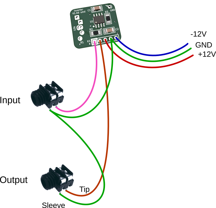
Connections
| Pin # | Usage |
|---|---|
| 1 | Input signal (+/-10V max for +/-12V power supply) |
| 2 | Output signal |
| 3 | +12V power input (+15V max) |
| 4 | Ground (GND) – This pin is common to both the input, output and power. |
| 5 | -12V power input (-15V max) |


Salut David… c’est Pedro, de Los Angeles… petite question [et SVP, mes excuses pour mon ignorance]: Comment peut on connecter ce petit Att/Inv dans le contexte d’un sistéme Eurorack? [Input, output, power]… Mais, espécialement si Je veut l’utiliser en “remote-mode”, c’est a dire, en dehors du “case” eurorack? [Je voudrais le prolonger avec des cables et le monter dans mon contrôleur à vent analogique, par example…] ..Merci en avance!
Salut Pedro !
Désolé pour la réponse tardive, je suis en plein déménagement ! ^^’
J’ai mis à jour la petite documentation fournie avec le kit : https://www.davidhaillant.com/wp/wp-content/uploads/inverter-1.0b-smd-BOM-doc-20160523.pdf
Peut être auras tu la réponse à ta question ?
Le plus important est d’alimenter le module avec une tension double (+12V et -12V, plus la masse (gnd)), la même qui est fournie par l’alimentation de ton “case” (boitier).
Dis moi si tu as besoin de plus d’explications. 🙂
David.