The DM77 is a Eurorack-compatible drum synthesizer inspired by the classic Coron DS8, featuring improved characteristics.
If you’re interested into the classic THT version, please visit DM77 V1.0b documentation.
Description

The DM77 emulates the classic disco drums sounds of the seventies, including bass drums, toms, and snares, as well as metallic sounds like bells, hi-hats, and more weird, spacey sounds.
It can also serve as a simple synthesizer voice, as its main oscillator tracks 1V/octave across several octaves.
To achieve its wide range of sounds, the module incorporates several functions:
- A main oscillator
- An LFO with adjustable modulation
- An envelope generator (Decay or Release)
- A Sweep function based on the envelope generator, with adjustable modulation
- A white noise generator with adjustable mix level
- A linear VCA
- and finally, an auxiliary external audio input.
The main oscillator generates a triangle waveform with a frequency range spanning from sub-audible to ultrasonic.
The Sweep effect follows the envelope signal, modulating the frequency of the main oscillator.
The second oscillator, a triangle LFO, also modulates the main oscillator’s frequency via the FM setting.
The Noise potentiometer adjusts the amount of white noise in the final signal, while the ‘Ext’ circuitry allows you to add an external audio source to the mix.
Finally, the output signal is controlled by a VCA, which follows the envelope settings (Release or Decay modes).”

In details
The circuits of the DM77 are derived from or inspired by several well-known synth circuit blocks, adapted and modified specifically for the DM77. Most of the circuits, including component values, are subject to changes and improvements. I strongly encourage you to experiment, hack, transform, and modify anything you like!

The SMD version
The SMD version of the DM77 introduces slight improvements and simplifications to the circuits, with its main advantage being the simplified build process. The DM77 is a relatively complex module, and assembling the THT version can be time-consuming. With the SMD components pre-soldered, only a few remaining THT components need to be soldered, allowing you to assemble your DM77 in under an hour.
The VCO
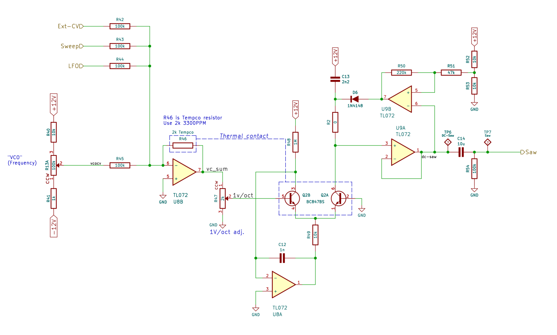
The main oscillator is a “saw core” VCO, loosely based on the Formant VCO. The comparator is an op-amp (U9B) instead of a CMOS gate, and the switching transistor has been replaced with a simple diode (D6).
The potentiometer R13 sets the main frequency, while R40 and R41 define the upper and lower limits of the base frequency range.
The frequency is modulated by 3 Control Voltages (CV): Ext-CV, Sweep and LFO, through R42, R43, and R44 respectively.
U8B is a summing amplifier that combines the CVs. R46 is the temperature-compensation feedback resistor, located near the NPN transistor pair Q2A and Q2B. R47 adjusts the 1V/Octave tracking behavior.
C13 is the capacitor where the saw tooth signal is generated: Q2B acts as a current sink, discharging C13 at a constant rate. U9A follows the voltage drop, while U9B compares this value to a reference voltage set by R52 and R53.
The raw saw tooth signal (DC-Saw) ranges from approximately +8V to +3V. When the voltage reaches around +3V, U9B triggers and sends a brief positive voltage spike to the negative side of C13 through D6. This spike causes C13 to quickly charge, resetting U9B and the capacitor begins discharging again.
It is important to note that the VCO relies at several places on the power supply rails for its voltage references. Any voltage variation on the rails will be noticeable in the stability of the frequency.
The waveshaper
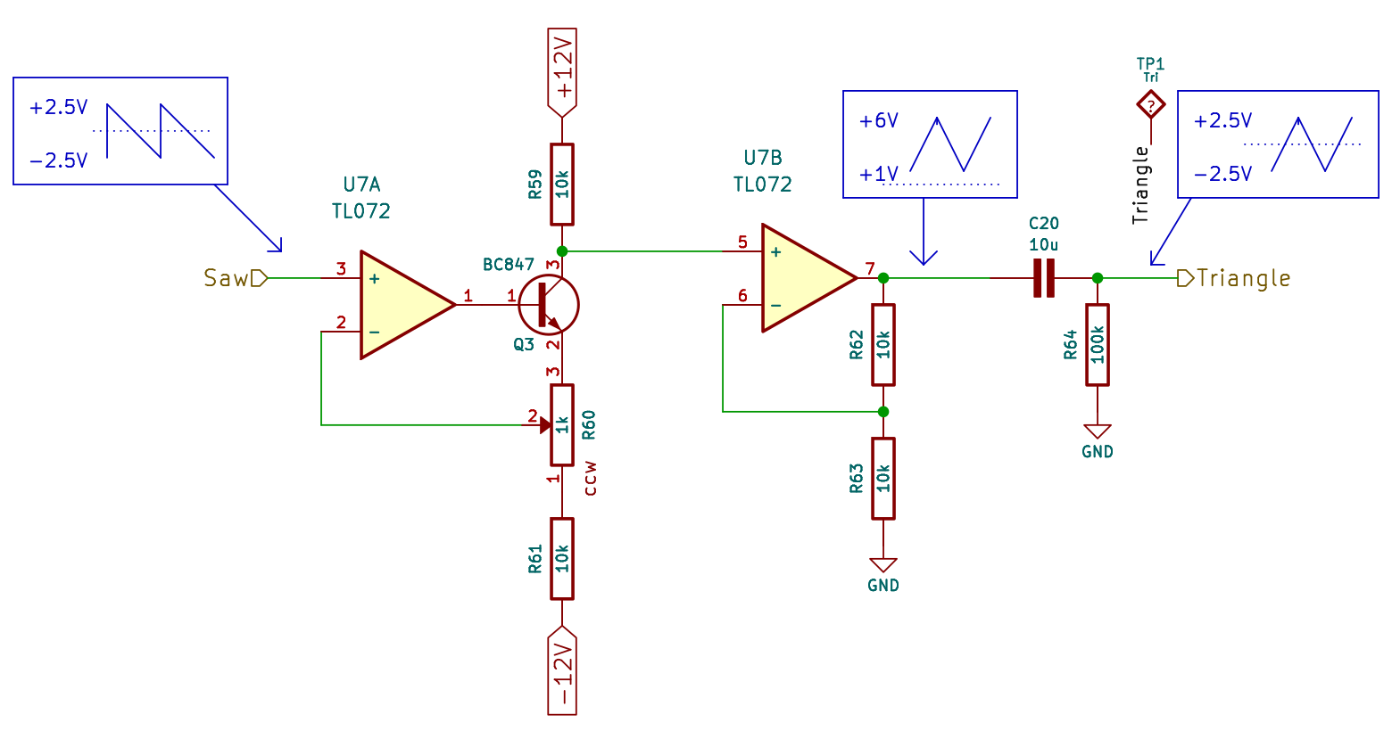
The AC sawtooth signal is fed into the triangle waveshaper circuit based on U7A and U7B. The negative portion of the sawtooth waveform is rectified, making it positive. The resulting signal is then adjusted using the trim potentiometer R60, which compensates for the offset between the positive and negative portions and removes any remaining artifact glitches. These glitches add high-frequency harmonics, which can be retained for enhanced “sound characteristics”.
The triangle waveform has a 5V peak-to-peak amplitude and is twice the frequency of the initial sawtooth signal.
The input stage
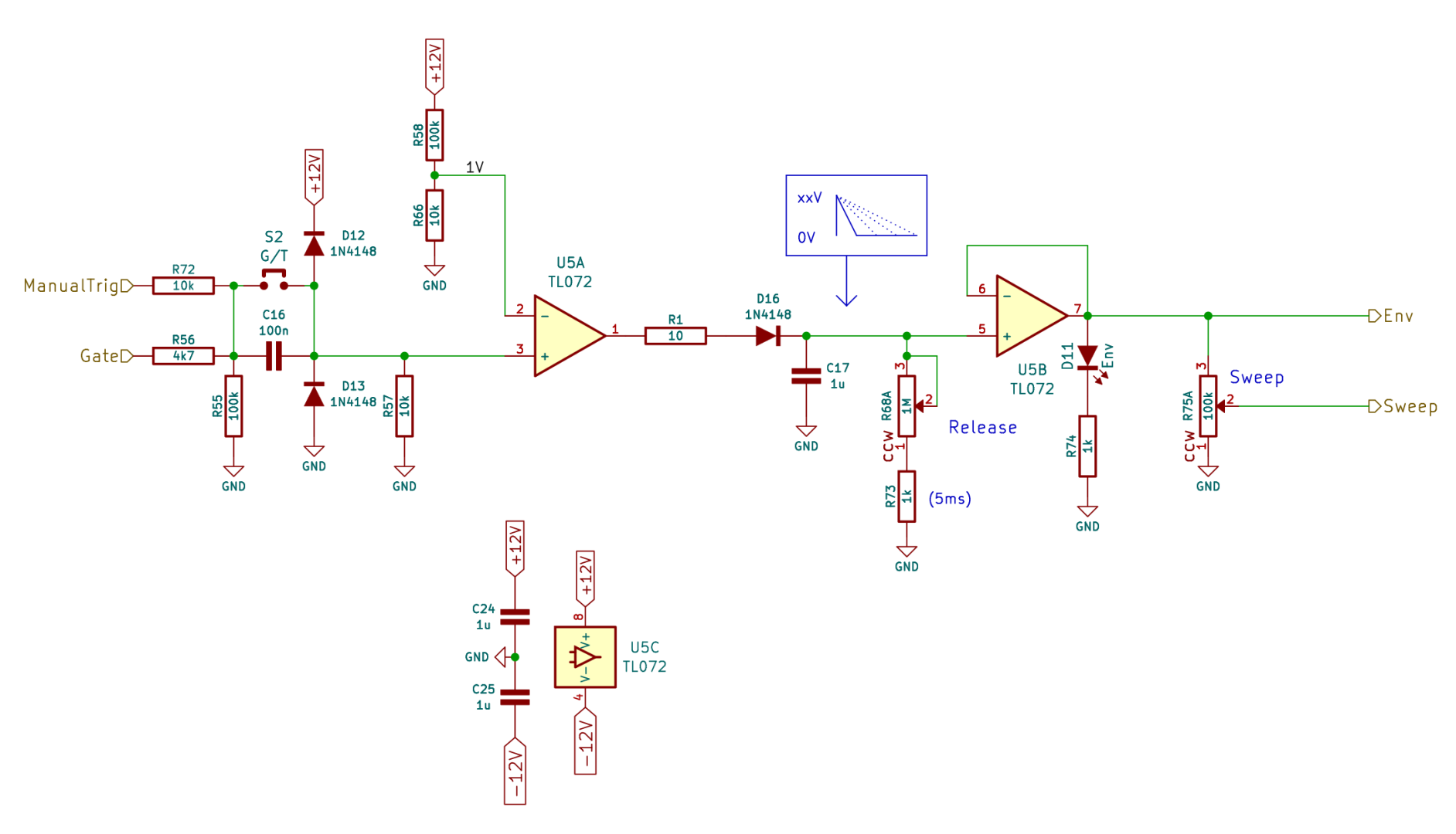
The Gate/Trig signal is fed through several passive filtering components to U5A. Diodes D12, and D13 remove the negative portion of the input Gate signal and protect the input of U5A by clipping excess voltages.
If switch S2 is open, C16 converts the Gate signal to a Trig signal. When S2 is closed, C16 is bypassed.
U5A detects any input signal above 1V. C17 charges immediately when D16 is forward biased by U5A. Then, C17 discharges through the potentiometer R68 which sets the discharge rate. U5B tracks the voltage on C17 and generates the envelope signal for the VCA. The LED D11 lights up when the envelope signal is present and gradually dims as it fades.
R75 is the Sweep potentiometer. It sends a fraction of the envelope voltage to the VCO, creating a sweep modulation effect (pitch envelope) that shifts the frequency from high to low.
The LFO
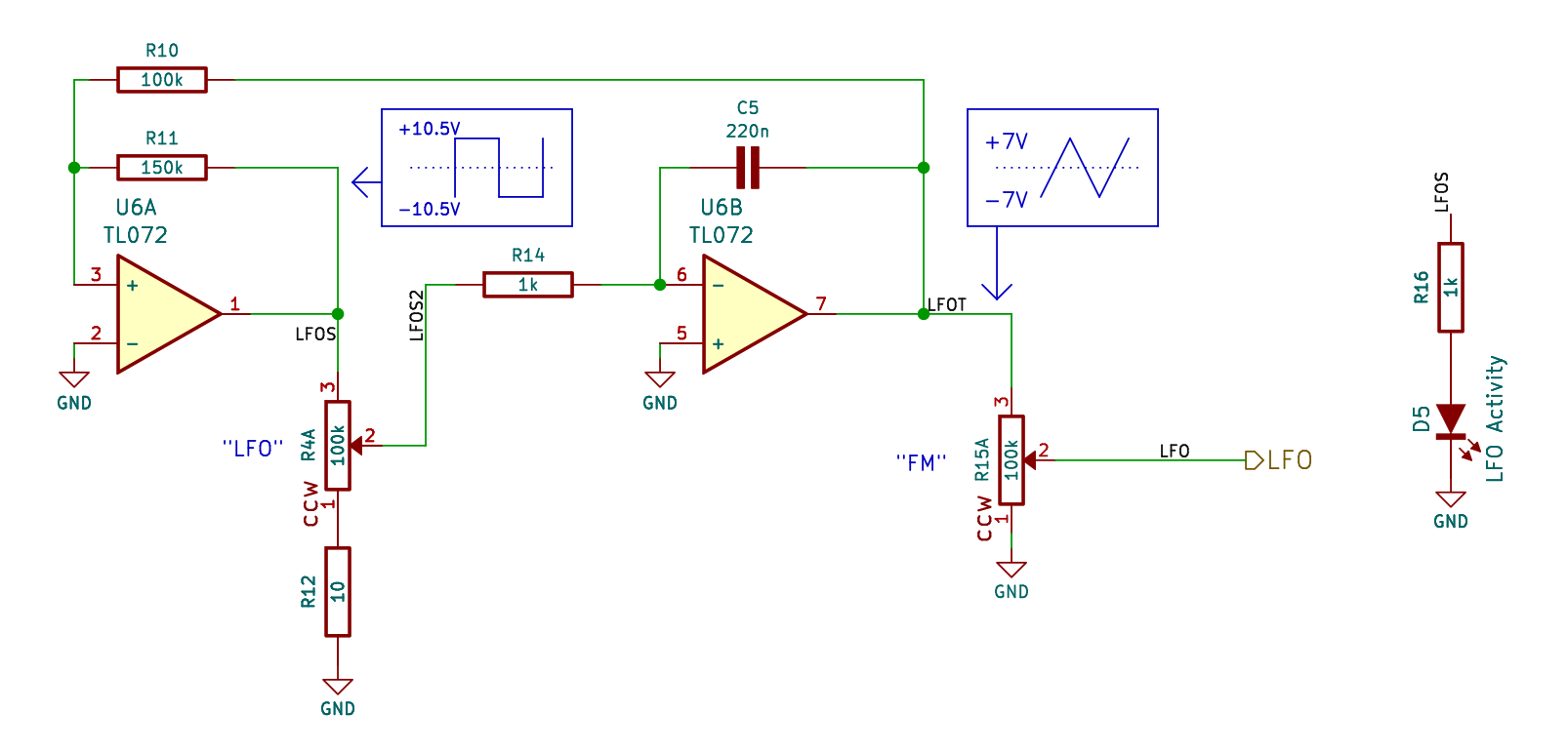
The second oscillator is a simple triangle waveform LFO. The potentiometer R4 sets its rate.
U6A functions as a Schmitt trigger comparator, while U6B serves as an integrator.
Capacitor C5 charges or discharges linearly at a rate dertermined by the position of R4.
When the LFOT signal reaches a defined voltage threshold, the Schmitt trigger swings its output (LFOS) to either +10 or -10V.
The potentiometer R15 labeled “LFO Mod.” sends a fraction of the LFOT signal to the VCO as a Control Voltage for FM modulation.
LED D5 blinks at the rate of the LFOS signal. If D5 is a bi-color LED, it changes color based on the sign of the LFO waveform (positive or negative).
The noise source
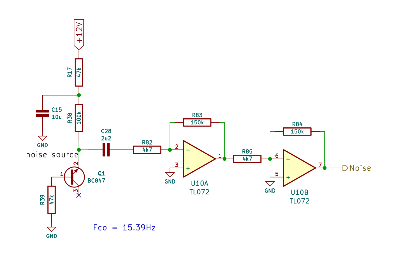
The white noise is generated by Q1, a reverse-biased NPN transistor. U10A and U10B amplify the noise signal to a usable level.
The network consisting of C15, R17, R38, and R39 decouples the noise transistor from the power supply rails. This ensures that the noise signal remains immune to power supply variations, while preventing the power supply rails from white noise contamination.
C28 removes any DC offset from the signal.
The collector leg of transistor Q1 is intentionally left unconnected.
The VCA
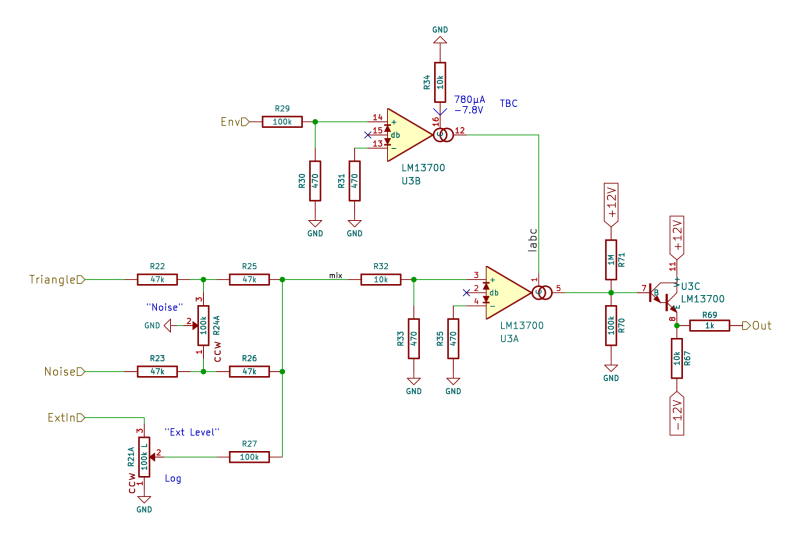
The Voltage Controlled Amplifier is the final stage in the DM77’s signal path.
Signals from the VCO, the noise generator and from the external audio input are mixed at the common node of R25, R26 and R27 (referred to as “mix”). The potentiometer R24 adjusts the balance between the triangle and noise signals.
U3 is an Operational Transconductance Amplifier (OTA). The gain of the VCA is controlled by the envelope signal (“Env”). The envelope voltage is converted to a control current (“Iabc”) by U3B and fed to U3A, where Iabc determines the gain of the OTA.
The current output of U3A is buffered by the integrated Darlington pair U3C.
See the schematics in “Documentation” section below.
Simulations
Component selection
All the components are Surface Mount Devices (SMD), except for the following:
- Potentiometers R13, R4, R15, R68, R75, R24 and R21
- The 4 jack connectors J1 to J4
- The “Manual Trig” push button S1
- LEDs D5 and D11
- Trimmers R60 (single turn), and R47 (multi turn)
- 10-pin Power input connector K1
- Jumper setting S2
- And finally, Tempco R46
The Surface Mount Devices (SMD) are pre-assembled.
Resistors
The SMD resistors are all in 0805 package, Thick Film, ±1% tolerance.
R46 can be a standard 2.2kΩ metal film resistor for a basic VCO, but in this case, the frequency will drift with temperature changes.
To reduce the temperature drift, use a linear positive temperature coefficient (PTC) resistor. Thonk offers a high-quality Akanehom 2k 1% 3300PPM tempco resistor.
Trimmers are vertical 25 turns 3/8″ trim pots. Inline pins. Set screw located on top.
Capacitors
The small-value capacitors are all 0805 MLCC, while the larger ones (10µF) are 1206 MLCC.
All capacitors must be rated for a minimum of 25V.
Active parts
The ICs are in SOIC-14 and SOIC-16 packages.
Transistors are SOT-23, except for the dual transistors, which are in SOT-363 packages.
The diodes are generic 1N4148 in SOD-323 packages.
LEDs
The LEDs are 3mm in diameter.
D5 can be a bi-color LED that remains on at all times, changing color when the LFO’s polarity swings. D4 is single-color LED, as the envelope signal is always positive.
I use the following references:
- L-934LYD (yellow LED)
- L-937EGW (bi-color Red/Green LED) – useful only for the LFO
8.5 or 9mm tall standoffs can be used to properly position the LEDs.
Jack sockets
You can find the WQP-PJ398SM jack sockets here:
- Thonk (https://www.thonk.co.uk/shop/3-5mm-jacks/)
- Synthcube (https://synthcube.com/cart/parts/plugs-jacks-fittings/3-5mm-audio-jack-thonkicon-type)
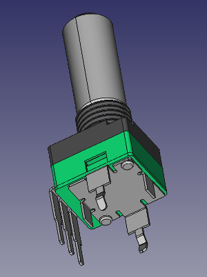
Potentiometers
You can find the potentiometers here:
- Thonk (https://www.thonk.co.uk/shop/alpha-9mm-pots/)
- Synthcube (https://synthcube.com/cart/parts/potentiometers-and-trimpots/alpha-single-gang-9mm-right-angle-pc-mount)
- Tayda (https://www.taydaelectronics.com/100k-ohm-linear-taper-potentiometer-round-shaft-pcb-9mm.html)
All potentiometers are linear, except for R21, which handles an audio signal; a logarithmic (Log) taper is a better choice. However, this parameter is not critical.
The decay/release potentiometer R7 is 500kΩ by default, but you can use a 1MΩ potentiometer for longer sounds, or a 100kΩ potentiometer for shorter sounds.
Push button
The manual Trig/Gate push button, S1, is a C&K D6 model. See Thonk (https://www.thonk.co.uk/shop/radio-music-switch/)
Component value changes
None to date.
Assembly guide
If you need help, please contact me.
Building the SMD version of the DM77 is simple and straightforward. Only the few remaining THT components need to be assembled.
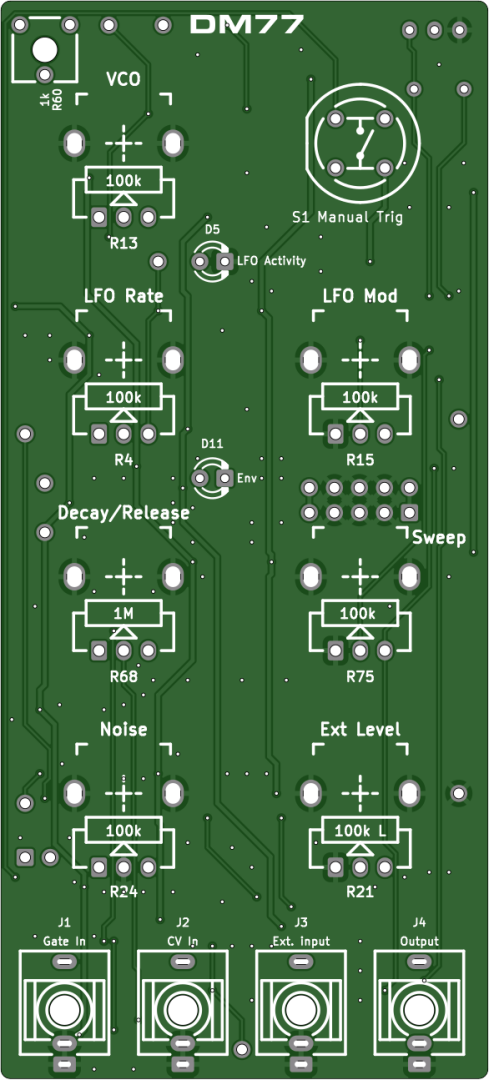
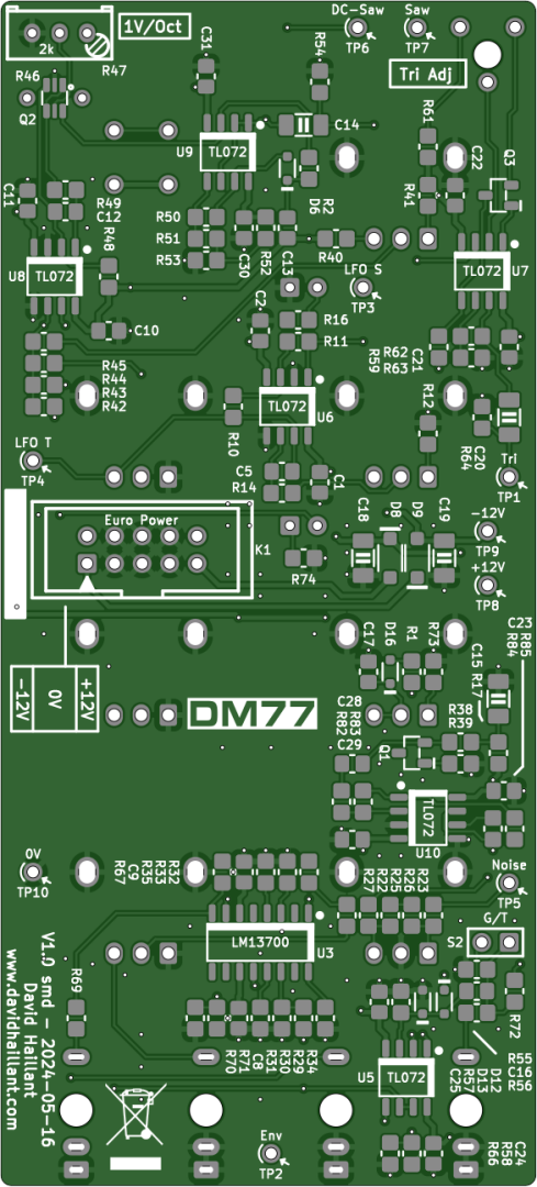
There is only one board
Unlike the THT version which had two boards, the SMD version is compact enough to fit everything on a single PCB.
Calibration and first tests
Powering on
Once the THT components are correctly soldered, double-check that the power input connector is properly oriented, your power cable is reliable, and your power supply is functioning correctly and compatible with the Eurorack standard before powering your module for the first time.
VCO calibration
The calibration process is the same as for any other VCO. The multi-turn trim potentiometer R47 adjusts the 1V/Octave conformance.
The required tools are:
- An accurate voltage source capable of delivering CV in 1V steps (0V, 1V, 2V, etc.). MIDI-to-CV modules work great for this.
- A frequency meter or tuner.
- A small flat-blade screwdriver.
- Your tongue at right angle – and some patience.
- A multimeter, because you always need one.
- And an oscilloscope (optional, but useful for monitoring the waveforms).
The modulation potentiometers R75 (“Sweep”) and R15 (“FM Mod”) must be turned fully counterclockwise (off). Noise potentiometer R24 must also be turned off (CCW)
If you are measuring the signal at the main output, or using a tuner, set jumper S2 to the closed position and turn the Release potentiometer R68 fully clockwise (for the longest release).
You can also measure the main oscillator frequency from test points TP6, TP7, and TP1.
- The first step is to apply no CV input (0V) and adjust potentiometer R13 to set the main oscillator frequency to a low value. If you are using a frequency meter, you can set the frequency to an easy-to-read value, such as 100Hz. If you’re using a tuner, or tuning by ear, set the main oscillator to precisely A2 (110Hz).
- Next, apply a 1V source on the CV input. The frequency of the main oscillator should double (to 200Hz or A3). If the frequency is flat, adjust trim potentiometer R47 to make the frequency slightly flatter. If the frequency is sharp, adjust R47 to make the frequency slightly sharper.
- Set the CV input back to 0V. The frequency should no longer be 100Hz (or A2). Adjust R13 to set the frequency back to 100Hz (or A2).
- Repeat step 2 until the frequency doubles exactly when 1V is applied to the CV input.
- Next, check if the VCO frequency doubles again with a CV of 2V. The frequency should be 4 times the base frequency (400Hz or A4).
- Repeat this for 3V, 4V, etc. The frequency should double for each additional volt applied to the CV input.
After several iterations, the VCO should remain in tune across multiple octaves. The number of octaves it stays in tune depends on several factors, including the quality of the transistors. The matching of the transistors does not affect how well the VCO tracks; it only corrects frequency drifts caused by temperature changes.


Waveshaper Calibration
The potentiometer R60 allow you to precisely remove the remaining artifacts from the saw to triangle conversion. By adjusting this potentiometer, you can remove the remaining high frequency harmonics still present. You can keep those harmonics if you prefer the harshness of the sound, or remove them completely to get a mellow triangle waveform.


Other measurements
Here are additional readings from the various test points.


In blue: “Env” signal at TP2
I built the SMD version – quick to build, easy to calibrate, and it’s a really fun module. It sounds great.