The SMT adaptation was a hobby project. The MFOS designs are the property of SynthCube.
If you want to buy PCB for the MFOS synths, please visit musicfromouterspace.com
Ray Wilson was the guy behind Music From Outer Space. He was a huge contributor to the Synth DIY scene. He designed a lot of cool projects, offered kits, schematics and a huge amount of tips and tricks for beginners. He even wrote a book on how to build an Analog Synth. MFOS kits and PCBs are still available through various resellers (see synthcube).

There’s an updated version available. Please, check the latest informations here.
I built, several years ago, a MFOS SoundLab MiniSynth. It’s a cool little analog synth, dedicated to beginners (with some technical backgrounds). It features 2 oscillators (Voltage Controlled), one white noise generator, one LFO, one AD generator, one LP/HP VCF and one VCA. It’s completely normalized and the routing is done by switches.
Even if it’s designed for simplicity, the panel wiring is a difficult step. In fact, MFOS projects are renowned for the amount of wiring required behind the panel, connecting pots and jacks to the PCB. And it can become a total mess quickly.
The second problem, if you’re into Eurorack format, is the size of the PCBs. They are pretty huge and hardly fit behind a 3U panel. Eventually, they’re attached at 90° from the panel using custom made brackets (or with Ray’s clever mounting brackets), making your modules really deep in your case.
So, as I wanted a second SoundLab Mini Synth to play with, but wasn’t really happy wiring again the same mess, I decided to make my own version of the PCB.
I took the original Schematics, edited everything in my favorite Electronic CAD KiCad and created a PCB, using almost only Surface Mount Devices.
Everything now takes place on a single PCB. And no wiring is required anymore.
The downside of a “no wire” project is obviously, when the PCB is finished, the lack of flexibility in user interface component placement. If you make a mistake in the design, placing a potentiometer in wrong position, too close to another pot or a switch in wrong direction, it’s difficult to correct it and you end up designing a new PCB.
So, designing an ergonomic, well thought user interface is a very important step. It’s the first step.

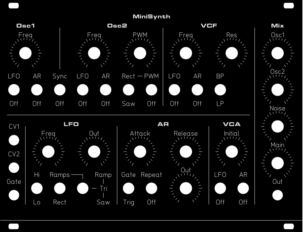
The position of the controls is different from Ray’s. It’s an arrangement I experimented on my previous build and gives me great satisfaction.

I use Front Panel Designer (by Schaeffer / Front Panel Express) for the job.
I then export the design to dxf and import it as a footprint in Kicad. It allows to accurately align UI PCB components to the front panel.
Then I check how much space everything take, measure how much space is left for other components.
For my SLMS version, I tried a 2 PCB solution, using board to board connectors, as I did previously in some projects (my DS8 clone for example).
I iterated the process several times, figuring which layout was the best compromise between space, usability, cost (big PCBs are expensive), components I could use, etc.

I ended with a one PCB solution, and everything in SMT, except for expo converter transistors, switches, pots and jacks, plus a couple miscellanies.
SMT was not my first choice. I wanted a TH solution because I had several components already in stock from my previous SLMS build. But, comparing the price of a bunch of resistors and the price of a second PCB, you can guess easily which solution is the least expensive.

I made, I think, a not-so-bad PCB of Ray’s classic synth. (Some errors were introduced though. See below.)
As Ray never put is work under Open Source or Open Hardware license, I can’t publish my SMT/Eurorack version in Open Source too. I only publish it as a non-profit/personal use only, as Ray did with its projects.
License clarification, as found on Ray’s website:
Everything on Music From Outer Space is free for non-commercial use.
Please feel free to use the information presented on the MFOS website to the fullest extent for non-commercial uses. You can make your own PCBs from the layouts and drawings we provide or design your own if you prefer. We appreciate a link to us if you blog or YouTube your work.
Build instructions
Now, if you want to build one for yourself, you need to know that I introduced, during the design process, several mistakes. I’m actually glad they were pretty obvious, easy to spot and to fix.
Gate Input

I spotted the first mistake while I was fulfilling the BOM and just after the Gerber files were sent to the PCB fab house. I used, in schematic capture, the wrong symbol for Q8. Instead of using a BC847, I used the symbol for a BC547. The pins are in a different order: BC547 is CBE (pin 1 is C, pin 2 is B and pin 3 is E). While BC847 is BEC.

So, for your build, don’t use a SOT package. Just use a TH TO92 BC547 for Q8 and solder it as on the picture below. It’s relatively easy to fix.

I must confess, the soldering job is not pretty on this one. I did it several times before figuring what the solution was.
The second mistake (actually, twice the same) is the inversion of pin 1 and 3 on Attack and Release pots.
To fix this one, you need to cut the PCB traces and rewire things correctly. Ok, I said it was wire-free… My bad.
If you don’t fix it, the controls are reversed.
Follow this scheme: cut traces where red marks, wire links as orange drawings.


Solder a wire as on the picture below:

VCO
Another mistake is, again, the inversion of 2 pins, but this time on the VCO2 Ramp/Rect selection switch. Again, the solution is to cut two PCB traces and rewire correctly.
Actually, this inversion is not really problematic, unless you use the Front Panel design I created. If you want, you can simply exchange the “Ramp” and “Rect” labels.
If you want to go into surgery, then follow the two drawings below:


Noise Gen
No problem here. The trick is to select the right transistor for the job. I have good results with the old noisy 2N1711 but a BC547 is a good option too. The amplification coefficient is so huge that, basically, any transistor is fine.
LFO
LFO is straight forward.
VCF
VCF has no problem either.
VCA
The biggest mistake I introduced is an interesting lesson.
It took me some time before I discovered what the error was. In fact, when I first powered my SLMS, I had absolutely no response, and worst, I had a short on the negative rail. Fortunately, the 79L09 did a very good job as its over-current protection fired instantly.
It wasn’t so simple to find the shortcut origin because, without power, there’s no sign of any short: using an ohmmeter was of no help. Then, if there’s no resistive short, it was obviously coming from one of the active components, with some weird action. Maybe a bad component? How to test when everything is soldered? It’s easier when you have socket mounted ICs. But here… how to figure what’s causing the short?
Well, two methods. The first one is to let the current flow and check who is heating too much, either with your fingers, or with a sensitive temp sensor. A thermal camera is the perfect tool for the job, but I don’t have one.
The second method is to use the resistivity of copper traces. Simply measure the voltage drops along the collapsing rail PCB traces. The lowest voltage measurement between the rail and your reference voltage (“gnd”) is closest to the shortcut. Same thing, the highest voltage measurement between power entry point and rail trace is the closest to the shortcut.
This method requires high shorcut current (copper resistivity is low) and requires a precision voltmeter.
In my case, temperature check was sufficient to find the chip causing the short.
I thought it would be a good idea to tie the “Amp bias input” pin of the unused halve of the LM13700 down to ground, in order to “reduce” things such as noise and power consumption…
I’d rather tied it down to negative rail!
In fact, letting Iabc pin floating is fine… as Ray did!

Long story short, to avoid trouble, do not solder U3 pin 1. Cut it or lift it:


Jack connectors
Last “mistake”, I used the Erthenvar Jack footprints for the 4 Jack connectors. Those Jacks connectors are fine. In fact, I use them often. But I misjudged their height, compared to other control components, pots and switches. “Erthenvar Jacks” (WQP-PJ301BM is 11.5mm height, where other components are 10mm height.
The right alternative is WQP-PJ398SM. To use them instead, you need to bend the ground pin and add a bit of wire to join the PCB ground pad.

BOM
For a complete list of components, sorted by values, with refs and comments, see below in downloads section.
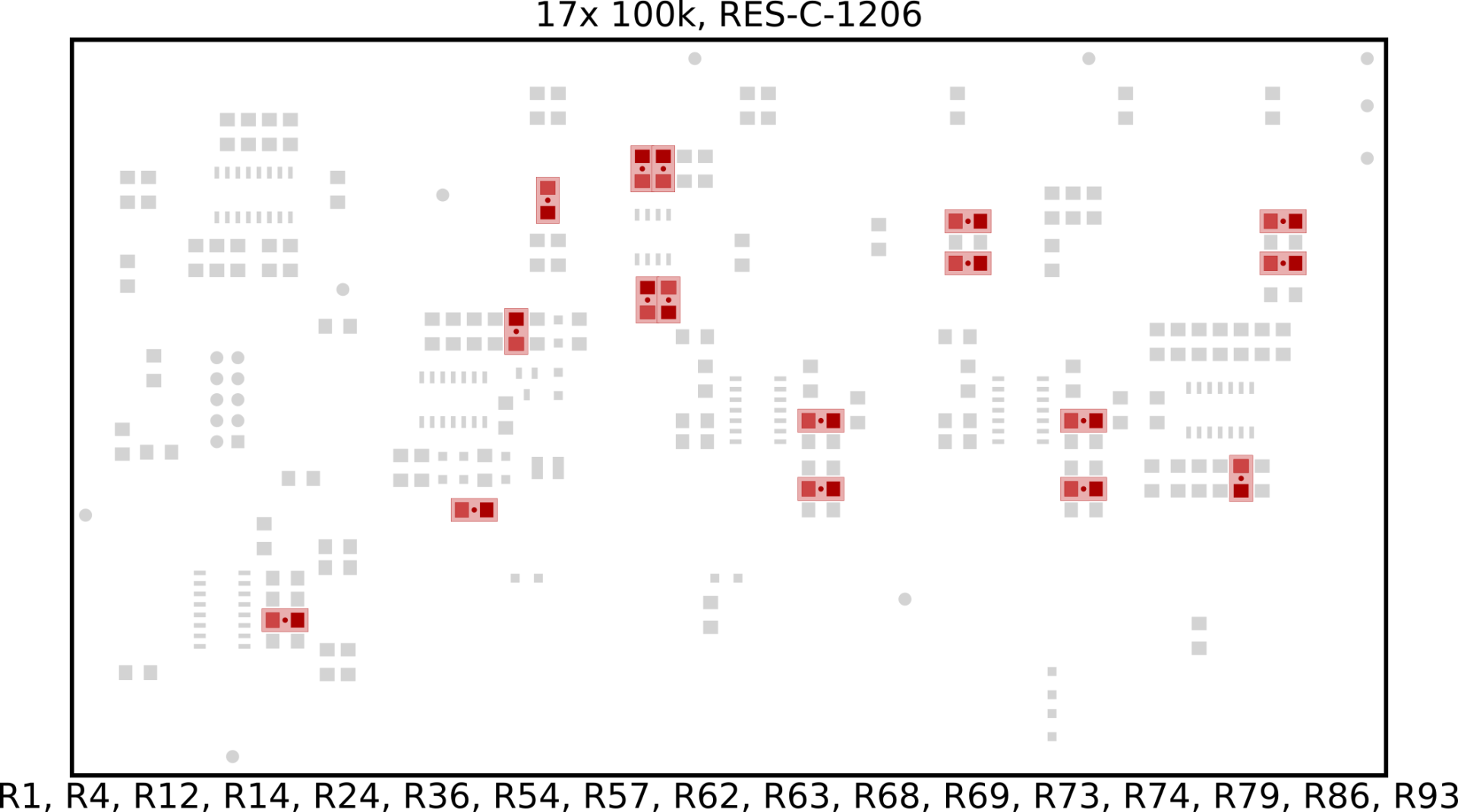
To help you with SMT component placement, I created a Component Map, one page by value, showing in RED where each component goes.

Switches
All switches are SPDT (Single Pole, Double Throw) with the exception of S16, which is a “3 position” SPDT with an additional central position (No Contact).
SPDT is ON – ON (Mouser: 506-A101SYZQ04)
SPDT “3 position” is ON – OFF – ON (Mouser: 506-A103SYZQ04)
The two Mouser ref should be ok for the job.
Sources for pots and jacks:
Potentiometers:
- https://www.thonk.co.uk/shop/alpha-9mm-pots/
- http://smallbear-electronics.mybigcommerce.com/alpha-single-gang-9mm-right-angle-pc-mount/
- https://www.musikding.de/Pot-9mm-100k-lin-Print-vertical
- https://erthenvar.myshopify.com/collections/9mm-potentiometers/products/smooth-shaft-vertical-pot
11.5 mm height Jacks (PJ301BM):
- https://erthenvar.myshopify.com/collections/accessories/products/3-5mm-vertical-jacks
- https://www.thonk.co.uk/shop/3-5mm-jacks/
- http://www.qingpu-electronics.com/en/products/wqp-pj3010bm-34.html
10 mm height Jacks (PJ398SM / “Thonkicon”):
- https://www.thonk.co.uk/shop/3-5mm-jacks/
- https://erthenvar.myshopify.com/collections/accessories/products/3-5mm-inline-jacks
- http://www.qingpu-electronics.com/en/products/WQP-PJ398SM-362.html
Downloads
- Schematics (PDF)
- Front panel design, Black/natural engraving (euro slms 33hp 20170325.fpd)
- Front panel design, Black/natural engraving, matching errors of version 1.0 : reversed AR pots and reversed VCO2 Ramp/Rect switch (euro slms with errors 33hp 20170325.fpd)
- BOM by value (.ods) and PDF version
- SMD Placement Map: 1 page per value (mfos-slms_picknplace_B.Cu-1.0-20171118.pdf)
- Top side map (mfos-slms_picknplace_F.Cu-1.0-20171120.pdf)
- Front Panel dimensions (slms-33hp-20180821-dimensions-20200406.pdf)


Hey David,
Can you also share KiCad files?
I am truly impressed !
Do you consider to (let) manufacture new PCBs ?
Do you intend to sell some boards ?
Kind regards
I want to update the PCB with some corrections before sharing CAD files.
I won’t sell SLMS boards, or kits. If I order an updated 1.1 version, then, I should have half a dozen boards to sell.
Hey there, this is a really nice project that I wanted to undertake some time ago!
Did you order a revised PCB in the end? I’d be glad to see one 🙂
Hi David,
are the changes/bodges already changed in the schematic or need to add? And any chance to share a KiCad File or sth. ? I want to build one for my rack since the min. for PCBA at JLC is 2 i would be doing two (which hopefully falls under private use?) ? Thanks anyhoo