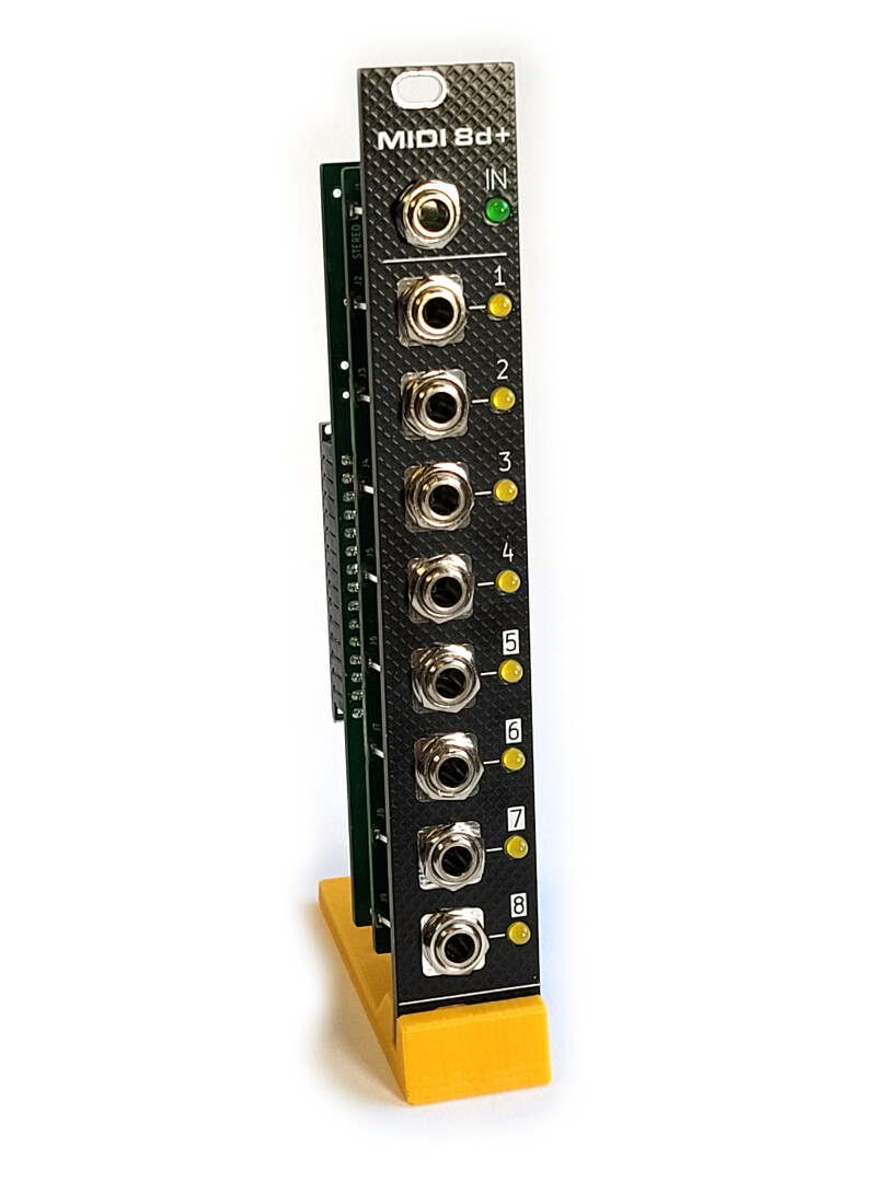
MIDI 8d+ is a very simple, yet super versatile MIDI-to-4-analog-and-4-digital-outputs module, that you can program and adapt to suit your needs.
It’s an upgrade from the previous MIDI8d module which is able to produce 8 digital outputs only (no analog outputs).
Compared to MIDI8d, the MIDI8d+ (note the PLUS) has the ability to produce 4 analog outputs in addition to 4 digital outputs.
These analog signals are generated by PWM and are filtered (low pass filter to attenuate the PWM noise) and buffered (the analog value doesn’t change upon load).

This is a very convenient, easy and inexpensive solution for adding Controls Voltages (CV) to your modular system.
However, PWM isn’t exactly perfect for sensitive and precise CV values (example, VCO tuning), but PWM is ok for anything else: CV for VCF frequency, CV for VCA, CV for delays, FM modulations etc. You can even produce audio signals.

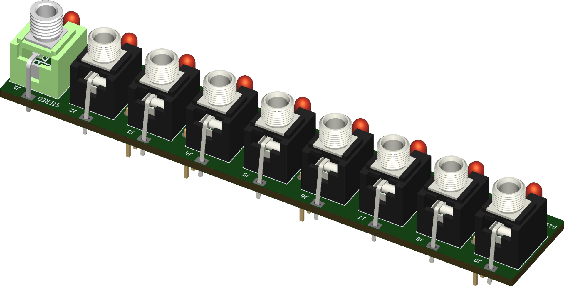
The PWM outputs are identified with the inverse color numbers.
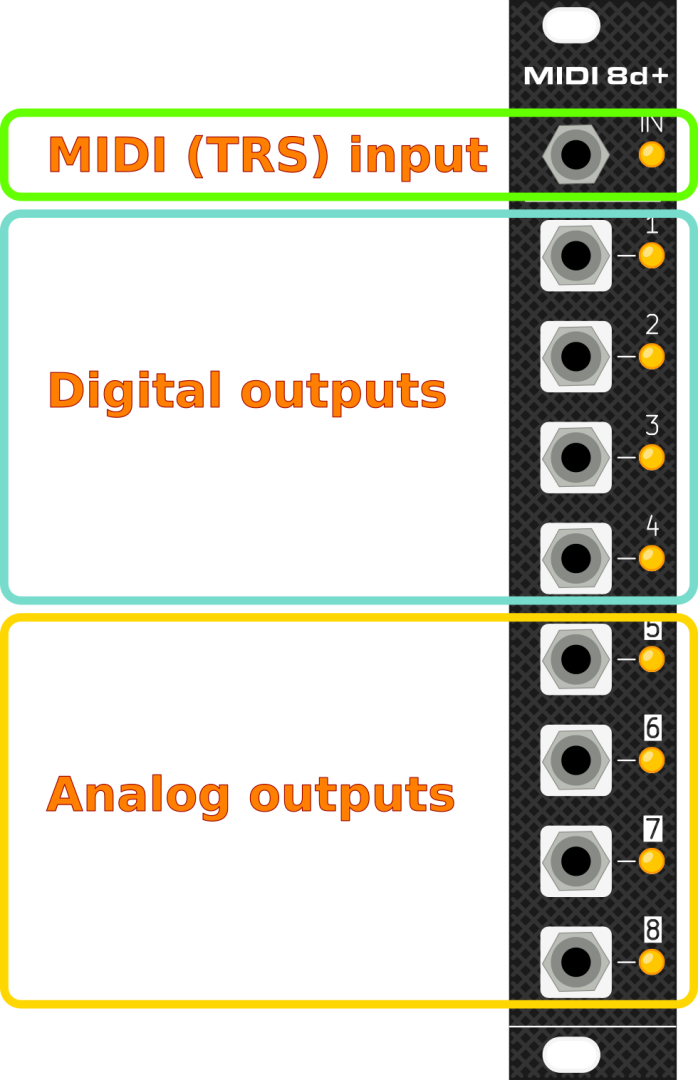
The first analog output (#5) has 16 bit resolution, while the 3 others (#6 to #8) are 8 bits.

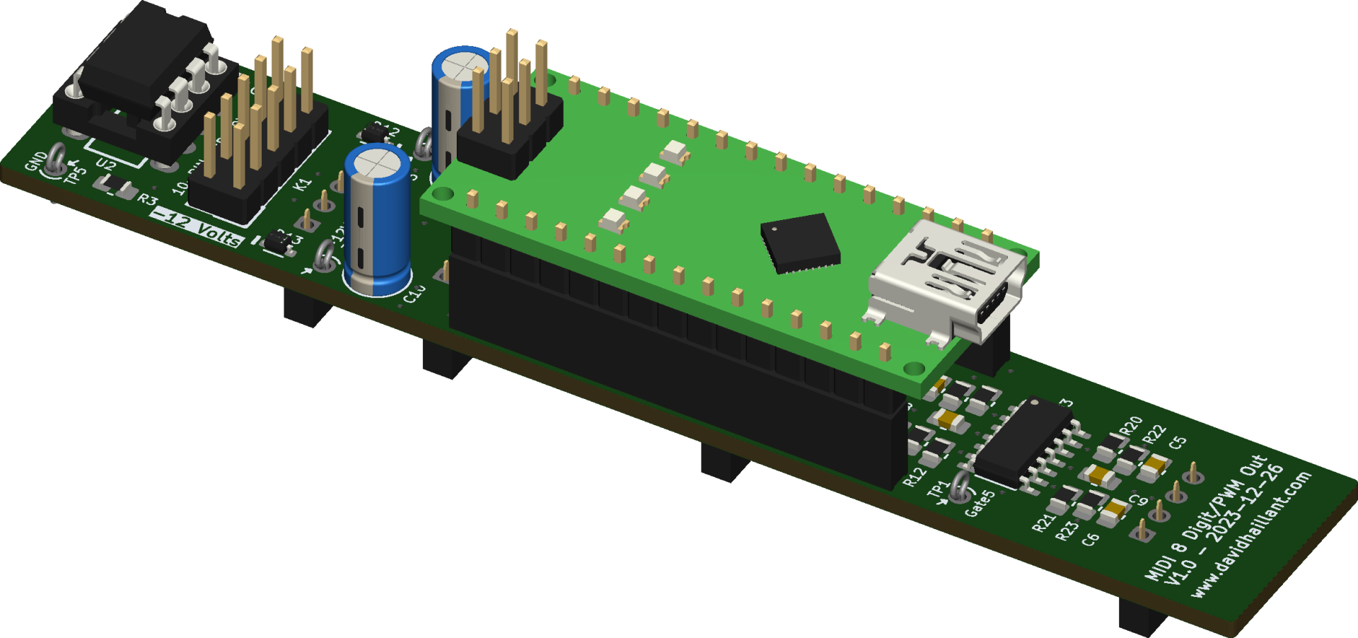
The core of the module is a classic Arduino Nano (ATmega328p) and can be programmed with the free Arduino IDE. It’s inexpensive, easy to program and widely available. Also, many sketches and library are available across the Internet to download.
The module is 4 HP wide and in Eurorack format. +5V rail is generated on-board by the Arduino Nano.
MIDI input
The MIDI input jack is a Stereo (TRS type A) connector.
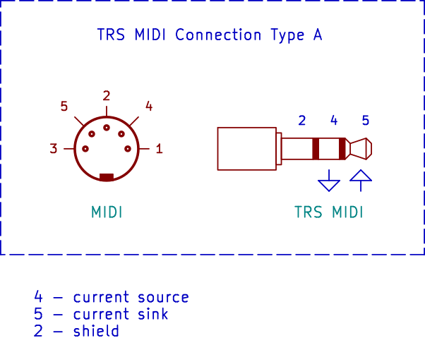
The Tip corresponds to the Sink signal, the Ring is connected to the Source.
Firmwares
Open source firmwares can be found here: https://github.com/dhaillant/midi8d/
Several examples are provided (Mono CV interface with velocity, 8 gates from MIDI channel 10, MIDI channel activity monitor, MIDI clock breakout, etc).
BOM
About C7 and C10
C7 and C10 are 5mm diameter, 2mm pin-pitch, Through Hole, polarized capacitors. They’re not shown on some pictures here, but they are recommended as they help against potential ripple while LEDs are switched on/off.
The usual capacitance value is 10µF and the Voltage rating should be greater or equal to 25 volts.
Be careful when placing them. They are polarized: align the white marking on the PCB with the white band on the capacitors.
Assembly
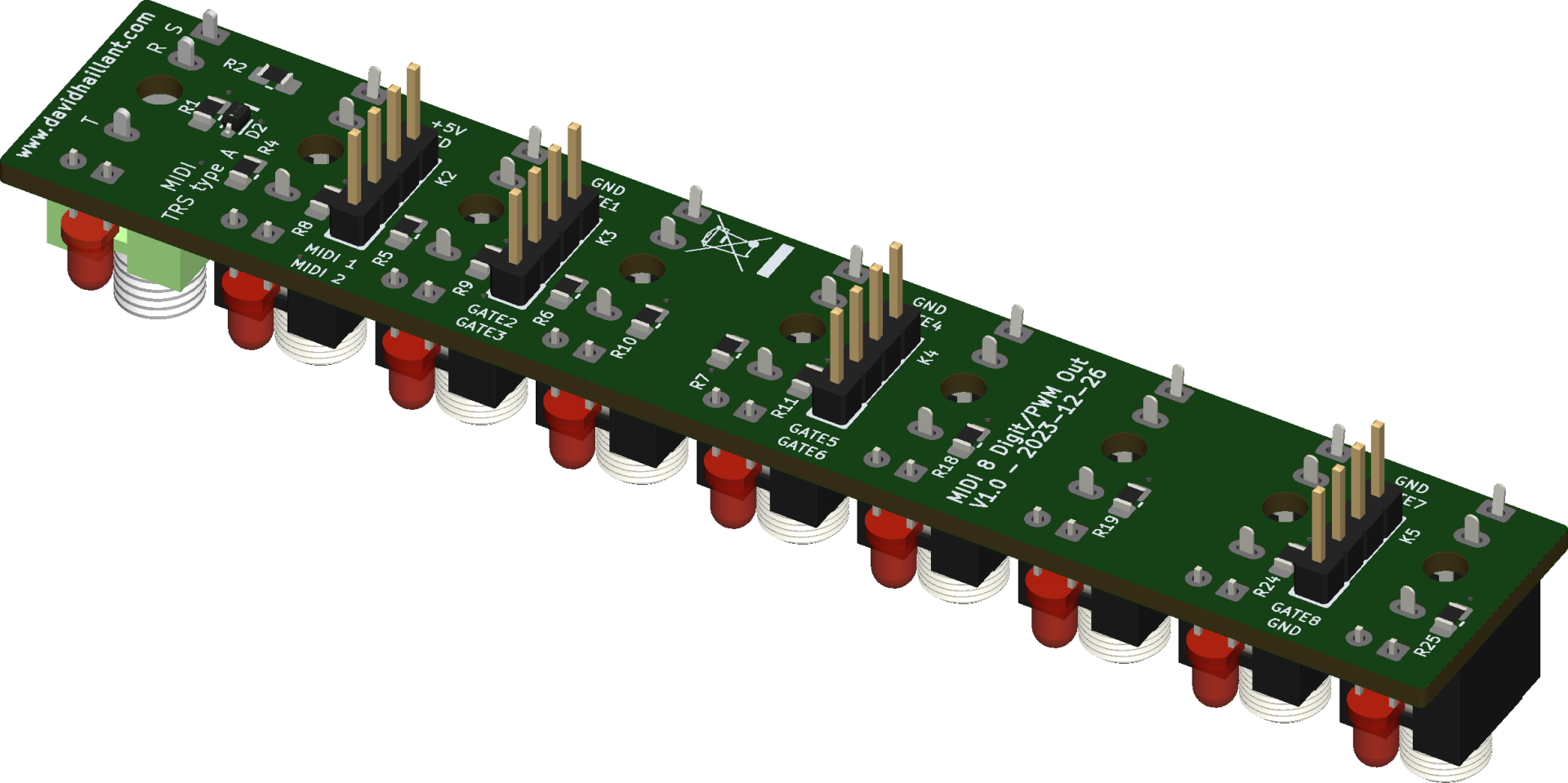
Front PCB
It’s important to solder the pin headers before the jack connectors. Once the connectors are soldered, you can’t access and solder the pin headers pads.
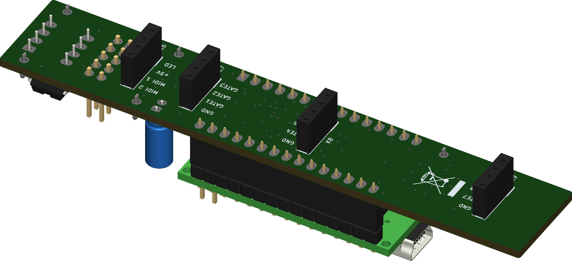
Rear PCB
Same as for the front PCB, I recommend to solder the four pin sockets before the headers for the Arduino Nano.
Documentation & downloads
Links
Buy PCBs, kits and assembled modules
You can buy the partial kit, with the main PCB and the front panel on ko-fi.com.
