I keep creating new 3D models for KiCad. This time I made some 9mm potentiometers I use in all my projects.
ALPHA / ALPS 9mm single turn Potentiometers:
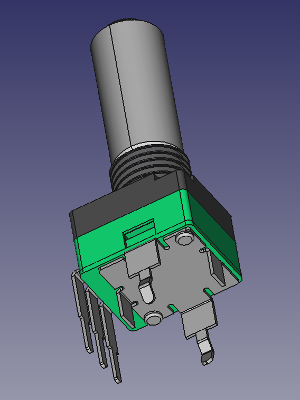
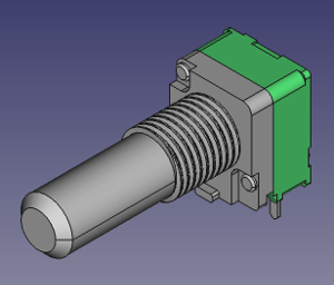
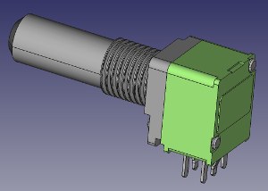
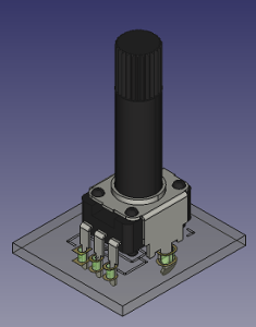
Download on Github : https://github.com/dhaillant/kicad-3dmodels/tree/master/potentiometers
I keep creating new 3D models for KiCad. This time I made some 9mm potentiometers I use in all my projects.
ALPHA / ALPS 9mm single turn Potentiometers:


Download on Github : https://github.com/dhaillant/kicad-3dmodels/tree/master/potentiometers
The SMT adaptation was a hobby project. The MFOS designs are the property of SynthCube.
If you want to buy PCB for the MFOS synths, please visit musicfromouterspace.com
This is an updated version of my SMT conversion of MFOS SoundLab MiniSynth!
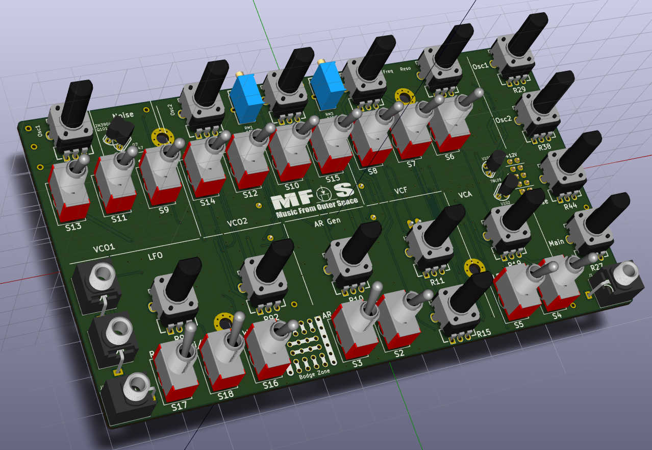
Continue reading MFOS SoundLab MiniSynth in SMT – 1.2 Update
I’m updating all my current designs in order to incorporate WRL/STEP 3D models. They provide a convenient way to check mechanical issues, especially with cases and front panels.
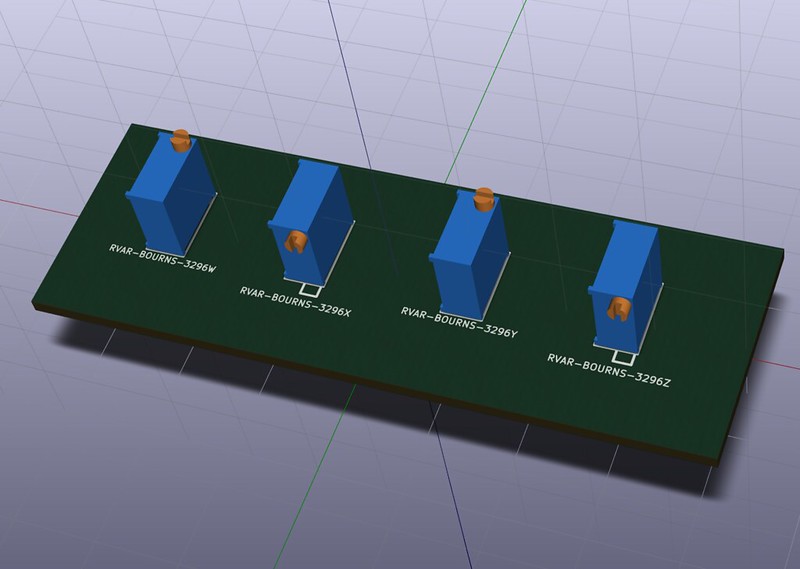
The Bourns 3296 3/8″ Trimpots are missing from the official KiCad 3D Library, so I decided to create my own.
It’s also a useful way to learn how to use FreeCAD and Github.
I’m also using kicad StepUp for model conversion, alignement and scaling.
You can find my 3D lib on GitHub here: https://github.com/dhaillant/kicad-3dmodels
Eurorack Stripboards have a dedicated zone layed out for Power Supply connection. You will find here some useful informations on how to use it.
About the power connector, I personnaly recommend to use boxed IDC Headers (HE10 style). They prevent from reverse and misaligned connections. But you can also use simple pin headers (breakable strips).
You also have the choice between 10 and 16 pin connectors. Both are fine. You can just use what is the most convenient to you. If you have plenty of 16/10 pin cables, then choose a 10 pin connector. If you have more 16/16 cables, then use a 16 pin connector…
It is customary to use a 10 pin connector if your module only requires -12/+12V rails. When you see a 10 pin connector on a module you immediately understand the module doesn’t require the +5V rail.
The 10 pin connector is soldered as on the picture below:
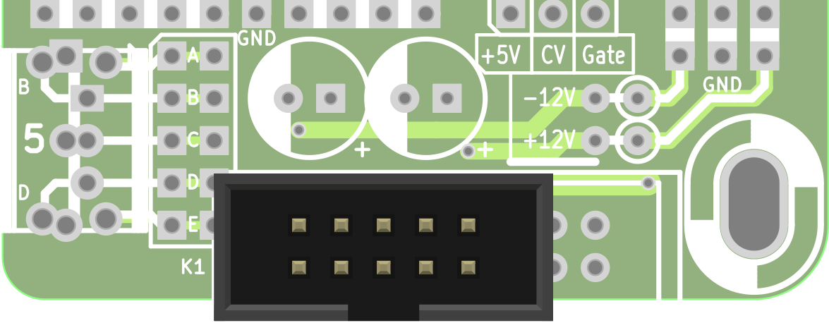
The capacitors are recommended only on rails where you actually draw current. Especially on modules with switching components (blinking LEDs…) who can create noise on your rails. 1 to 10µF is ok. The voltage rating should not be under 25V.
Diodes protect your module. Wire them as shown on the picture below:
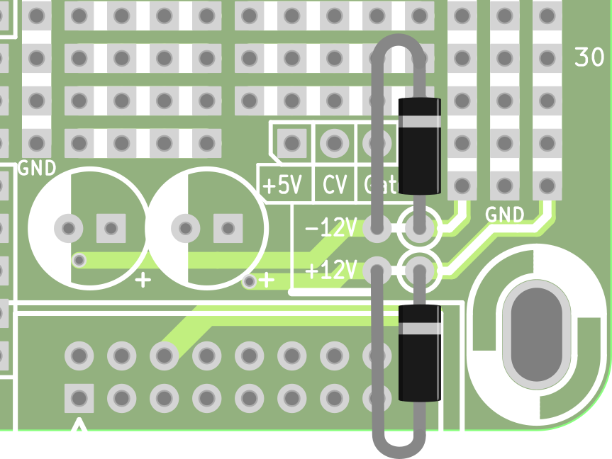
Or you can just skip them and use jumper links instead. The diodes are only for protection purpose. They block reverse voltages in case of bad Power Cable or incorrectly powered Bus.
Any 1N400x is ok. Use Schottky Diodes instead if you require lower forward voltage drop. Silicon Diodes such as 1N400x will lower the power rail by, at least, 0.7V: 12 – 0.7 = 11.3V only. Schottky Diodes have a forward voltage drop of roughly 0.4V, giving you 11.6V on your rail.
NB, the diodes should have been placed before the capacitors to create an effective LP filter… and help protect the filtering caps too in case of reverse Power supply polarity. So I encourage you to add a capacitor on each rail after the diodes instead of the initial dedicated area.
I made some scope measurements to help understand and debug faulty MFOS SLMS in SMT version.
My scope is not very accurate and the tested unit is far from perfect, but at least, it gives a pretty good idea of expected signals on the Test Points.
First signal to check is VCO1 (TP201). Put VCO1 Frequency pot in middle position (50%), LFO and AR switches on Off position:
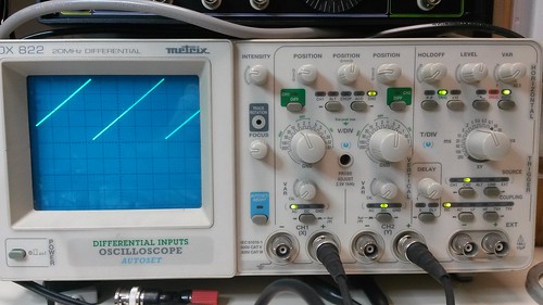
Continue reading Debugging MFOS SLMS
The SMT adaptation was a hobby project. The MFOS designs are the property of SynthCube.
If you want to buy PCB for the MFOS synths, please visit musicfromouterspace.com
Ray Wilson was the guy behind Music From Outer Space. He was a huge contributor to the Synth DIY scene. He designed a lot of cool projects, offered kits, schematics and a huge amount of tips and tricks for beginners. He even wrote a book on how to build an Analog Synth. MFOS kits and PCBs are still available through various resellers (see synthcube).

Continue reading MFOS Sound Lab Mini-Synth in SMT
KiCad has been updated to 4.0.x branch and it is strongly recommended to use it for all your new projects, instead of the good old BZR 4022 from 2013.
But sometimes, when you want to open an old design without too much trouble, it’s more convenient to just install the old version.
Continue reading How to install KiCad 2013-07-07 BZR 4022 on Ubuntu 64
LEDs are polarized components. Backward, they just don’t light on.
How to recognize the polarity of a LED?

Continue reading How to determine Through Hole LED Polarity?
 Hand soldering Surface Mount Devices (SMD) scares a lot of builders, but it is easier than what it looks like. Even sometimes, it’s easier than soldering classic Through Hole Components. Really!
Updated on March 24th, 2021
Continue reading How to Hand Solder SMD
A quick post about an old design.
This is a simple 3 mono input mixer.

Continue reading Simple Mixer with 3 Mono Inputs