Eurorack Stripboards have a dedicated zone layed out for Power Supply connection. You will find here some useful informations on how to use it.
About the power connector, I personnaly recommend to use boxed IDC Headers (HE10 style). They prevent from reverse and misaligned connections. But you can also use simple pin headers (breakable strips).
You also have the choice between 10 and 16 pin connectors. Both are fine. You can just use what is the most convenient to you. If you have plenty of 16/10 pin cables, then choose a 10 pin connector. If you have more 16/16 cables, then use a 16 pin connector…
It is customary to use a 10 pin connector if your module only requires -12/+12V rails. When you see a 10 pin connector on a module you immediately understand the module doesn’t require the +5V rail.
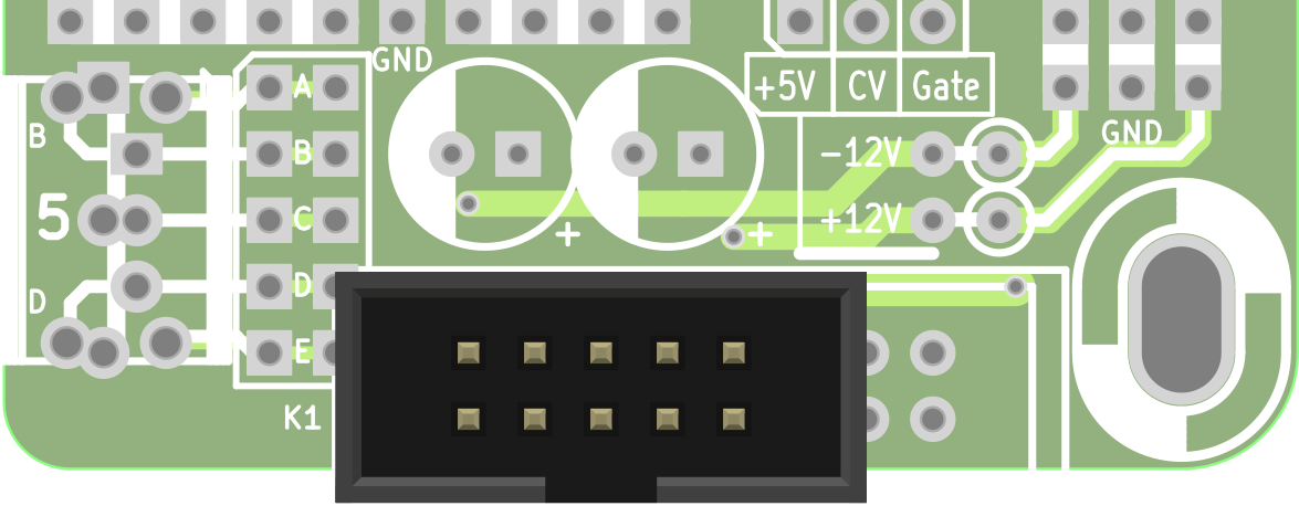
The 10 pin connector is soldered as on the picture below:

The capacitors are recommended only on rails where you actually draw current. Especially on modules with switching components (blinking LEDs…) who can create noise on your rails. 1 to 10µF is ok. The voltage rating should not be under 25V.
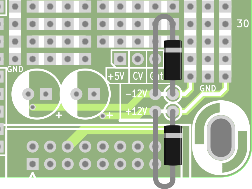
Diodes protect your module. Wire them as shown on the picture below:

Or you can just skip them and use jumper links instead. The diodes are only for protection purpose. They block reverse voltages in case of bad Power Cable or incorrectly powered Bus.
Any 1N400x is ok. Use Schottky Diodes instead if you require lower forward voltage drop. Silicon Diodes such as 1N400x will lower the power rail by, at least, 0.7V: 12 – 0.7 = 11.3V only. Schottky Diodes have a forward voltage drop of roughly 0.4V, giving you 11.6V on your rail.
NB, the diodes should have been placed before the capacitors to create an effective LP filter… and help protect the filtering caps too in case of reverse Power supply polarity. So I encourage you to add a capacitor on each rail after the diodes instead of the initial dedicated area.